Figure 1. Section drawing shows thread balls in contact with pitch line of internal thread.
INTERNAL THREAD INSPECTION MTG Inc decided to look for answers by studying one of the most successful methods of gaging external threads, the 3-wire system. No one had ever seriously considered this
system for internal threads before because it was obvious
that the physical characteristics of wires made it impossible
to deploy and seat them in the tight convolutions of a female
thread.
But the principle was sound, so MTG Inc overcame the physical problems
by substituting floating balls of Best Wire sizes for the
actual wires. Held captive in caliper fingers and mounted
on an indicating gage frame, the balls could be made to simulate
three-wire inspection in internal threads (Figure 1).
LESS GAGING
PRESSURE
The use of balls, incidentally, eliminates perhaps the only significant shortcoming of wires. The problem is spelled out in Screw Thread Standards for Federal Services, under the heading Limitations of Three-Wire Measurement of External Threads: "When the lead angle and diameter of a thread are such that double contact of the measuring wires occurs, it will be necessary to check the pitch diameter by means of balls rather than wires. For accurate measurement with wires, single contact on each flank must occur. Measuring wires can be used if the following formula is satisfied for a specific thread." Then follows a lengthy compensation formula developed by Werner F Vogel.
Because of the possibility that wires may make double contact
in threads of certain lead and diameter combinations, Vogel's
equation calls for increased gauging pressure to seat the wires; as
much as 2.5 pounds (1.13kg) for a 1/2"-20 UNF thread. This may result in deformation
of wire and thread.
Replacing the wires with balls as MTG Inc has done eliminates
seating problems by making spheres rather than cylinders the
method of contact. Gaging pressure need be only about 1 ounce (0.03kg),
or enough to satisfy the inspector that contact pressure is
sufficient to register the size.
HOW ERROR IS ISOLATED To understand how the ball principle isolates thread aspects
for errorless measurement, let us first consider the key dimension
in any thread; the pitch diameter. By definition, the pitch
diameter is an imaginary cylinder along which each cut thread
and each web of intervening metal have the same width: one-half
the pitch, or P/2 (pitch divided by 2).
Traditionally, the pitch diameter has been checked with thread
plug gages. If an inspector could enter the "GO" plug but
not the "NOGO", the pitch diameter was considered to be within
tolerance. Should the "GO" fail to enter; general practice
is to deepen the cut until it did. Conversely, should the
"NOGO'' enter, the cut is made shallower to prevent
its entry.
The blind spot in this procedure is ASSUMED perfection
in all other aspects of the internal thread. It ignored the
fact that a thread cut to perfect depth will gage undersize
if there is lead error, because the mismatched leads of the
thread and the plug gage will have interference. By the same
token, a thread cut oversize and having lead error can pass
thread plug inspection if the interference is not enough to
block the "GO" but does prevent the "NOGO" from entering.
Figure 2. Floating action of the balls cancels out pitch errors in the metal between cuts (V) whether the error is minus as at (A) or plus at (B).
The floating ball system cannot be deceived by errors in lead
or helix, no matter how severe or erratic (as in drunken threads),
because the balls float laterally to find a perfect seat in
the cuts regardless of the width of the metal between cuts (Figure 2). The balls are grade 10 solid carbide, finished to Best Wire
sizes, and will positively establish the accurate pitch diameter measurement since they measure diametrically across the
threaded hole from cut to cut, not from cut to metal.
What is the importance of gauging from cut to cut? Simply
stated; all diameters of an internal thread are functions
of depth of cut. The cut is the constant; an exact matrix
of the cutter at every point along the thread. The metal between
cuts; however; is an unknown remainder whose P/2 (pitch divided by 2) width is
a linear function dependent on the accuracy of the lead. A
lead with a plus error will widen the metal between cuts;
a minus error will narrow it; an erratic lead will result
in inconstant widths. Unless the lead has been proved perfect
in advance, checking the pitch diameter by using the metal
as a gauging point is futile.
ISOLATING SUBSEQUENT
ASPECTS With
the ability to isolate and accurately check the pitch diameter
it becomes a simple matter to inspect the remaining thread
factors one at a time; isolating extraneous errors at each
step. In the MTG Inc system, the same gage frame is provided with
additional pairs of fingers; each with a separate function.
HOW ACCURATE? The MTG Inc system is so accurate it can be used to certify solid-style thread
ring gages on the job. In the MTG Inc system; much thought has been given to the elimination
of normally inherited errors.
The gage does not
measure. The gage compares the work piece against an accepted reference,
such as a plain ring gage or gage blocks, and shows any variation
on a dial indicator or electronic comparator.
The measurement fingers move
in one plane only, along the axis of the indicator, so no
radial or angular "scissors effect" errors can be introduced.
Problems of taper and out-of-round will not fool the system
because its point-contact fingers reveal such conditions by
displaying various readings when they are moved from one location
to another around or along the thread.
Repeatability of the MTG gage is excellent since there is
nothing to change successive readings except surface contaminants. Careful cleaning of critical parts can overcome this.
Thread
plug gages can neither isolate compound errors in female threads
nor reveal the amount of error. They merely suggest that something
is wrong.
The MTG Inc system lets the producer of internal threads
make his own step-by-step analysis with this hand-held gage in
a few minutes. Required data is obtained by use of interchangeable
fingers shown in the chart below.
Most significant of the fingers is ''J'', which contains two
floating balls of Best Wire Size'. These balls make contact
at the P/2 (pitch divided by 2) width, or pitch circle of the thread grooves. Because
they float in their pockets, the balls will seat at the pitch circle whether
the lead is short, long, correct or drunken. Finger "J" is
used in conjunction with every upper finger in the thread
series except the "Functional", and provides an identical
base line in every case!
MTG ZONAL METHOD
Figure 3.. Floating action of the balls cancelled out pitch errors in the metal between cuts (V) whether the error is minus as at (A) or plus at (B).
PITCH DIAMETER Fingers "A" and "J" both contain grade 10 tungsten carbide balls with the Best
Wire Size. These two fingers give a reading which excludes lead error but
not angular errors. Pitch Diameter fingers can be used interchangeably for right hand or left
hand threads.
TAPER AND OVALITY Use fingers "A" and "J" at intervals along thread for
taper and around the thread for ovality.
INCLUDED ANGLE Use fingers "D" and "J". The ball in "D" is smaller than
in pitch diameter finger "A", and should seat a prescribed
distance deeper. If it does not, angular error is present.
The degree of error and its effect on PD can be determined
by a formula.
MAJOR DIAMETER Use fingers "B" and "J"
UNEQUAL HALF
ANGLES Opposite finger "J", use "E"; then either "F" or "G".
"E" has full flanks, while "F" and "G" are limited to 0.1H
contact. Where half-angles are unequal, the thread groove
will be tilted, and ''E'' will seat more shallow because its
broader contact surfaces will meet greater interference from
the tilted groove. The degree of tilt and its effect on PD
is available through thread specification publications.
MINOR DIAMETER
Concentricity between minor and PD. is measured by using fingers
"C" and "J~ and rotating the workpiece or gage. Minor diameter
size, roundness and taper are checked with a pair of "C" fingers.
FUNCTIONAL
(MAXIMUM MATERIAL) DIAMETER
Paired fingers "C' are helically ground for a single PD.,
pitch/lead combination which will measure the net effect of
all errors.
SIMPLE
SETTING METHODS The MTG
gage is set "over the balls" or "over the crests" with gage
blocks, micrometers, super micrometers, or plain cylindrical
ring gages. No threaded masters are needed.
SETTING THE PITCH DIAMETER FINGERS
The pitch diameter setting equals the pitch diameter (low,
nominal or high) plus the ball radius. The ball diameter is
etched on the pitch diameter fingers.
SETTING THE FUNCTIONAL FINGERS
Functional fingers are marked with a specific setting size (example: OD 0.7501).
SETTING MINOR DIAMETER FINGERS
Paired minor diameter fingers are set exactly to the minor
diameter size. When a single minor diameter finger is used
opposite a ''J'' finger to check concentricity, no precise
setting is required.
SETTING ALL OTHER FINGERS
All contacts (except minor diameter) that are used opposite
contact "J" are marked with a constant (CO) dimension (examples: CO+0.0214; or CO-0.0251). Setting size is equal to the pitch diameter setting
plus or minus the constant dimension.
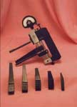
MTG INTERNAL GAGE COMPONENTS
(click image for full view)
INTERNAL
GAGE FRAMES The
basic internal gage frames are available in two models.
The G-600 with a capacity from 0.190 inches to 5 inches
basic and the G-1200 with a capacity from 6 inches
to 18 inches. The gage frames are extremely accurate,
0.000050 inch repeatability is guaranteed. The system
was designed to take the abuse of shop use although
it is precise enough for the requirements of the quality
control or metrology laboratory. Two extension kits
are available. The G-600X increases the capacity of
the G-600 frame to 6 inches basic and the G-1200X
increases the capacity of the G-1200 frame to 24 inches
basic. The gauging pressure of both internal frames
can be adjusted by the operator from maximum to negative
pressure thereby allowing very thin wall parts to
be measured.
(click image for full view)
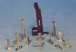
INTERNAL
GAGE FINGERS MTG
offers more sizes, types, and reaches of internal
fingers than any other gage manufacturer. Fingers
can be manufactured to measure most every thread form
including Unified, Buttress, Acme, Stub Acme, Metric,
Whitworth, Lowenherz, Ball, 40 Degree Worm, Aero,
and Square. Additional geometries are available for
bearing races, grooves, bores, tapered bores, gears,
splines, and dovetails. Six different lengths are
available.
1.5U .................Basic Length 1.25 Inches..........Under
5/8 In. Diameter
1.5 ................... Basic Length 1.5 Inches.......... 5/8
In. Diameter & Over
2.25 ..................Basic Length 2.25 Inches......... 3/4
In. Diameter & Over
3.0 ................... Basic Length 3.25 Inches........ 1.0
In. Diameter & Over
4.0 ................... Basic Length 4.12 Inches........ 1.0
In. Diameter & Over
5.0. .................. Basic Length 5.0 Inches...........1.5
In. Diameter & Over
(click image for full view)
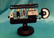
TAPERED
INTERNAL THREADS MTG
now enables the operator or quality control inspector
to accurately measure internal tapered threads. No
tapered set masters are required. Simple L1 location
setting is designed into the system. The system can
be hand-held or stand mounted. Fingers are available
to measure pitch diameter, functional diameter, minor
diameter, included angle, and full form (single thread)
on 60 degree tapered threads.
(click image for full view)
DEEP
HOLE DIAMETERS The
MTG Telescoping Tube System (TST) is far more accurate
than its competitors who use long segments that bend
and deflect. The system can be used on either the
G-600 or G-1200 internal gage frames. The reason for
its accuracy is the fact that it creates a "Linear"
measurement. The TST System uses TST inserts which
are available in all the geometries listed for the
internal fingers. Diameters as large as 36 inches
or more may be measured. There are three standard
lengths available, 5 inch reach, 8 inch reach, and
10 inch reach.
(click image for full view)
INTERNAL
BORES AND GROOVES Only
with the MTG System can a bore diameter, internal
groove diameter, and their concentricity to each other
be measured with a single gage and set-up. This capability
is due to the "MTG SQUARING PLATE" accessory. Four
different squaring plates are available. All plates
are slotted through their centers permitting the use
of all our internal fingers. Squaring plate arms are
adjustable for length so the reach of the fingers
into any bore can be set to the desired dimension.
BORE
& GROOVE INSPECTION
CHECKING THE BORE Banking
the workpiece against the squaring plate keeps the workpiece
straight, so it is necessary to rock it in only one plane to
find the high point of the diameter. The squaring plate may
be moved in or out to permit gaging at any depth. CHECKING THE GROOVE
After bores have been inspected for diameter, the gage is quickly
reset to groove diameter and the squaring plate moved to a point
that sets the fingers for groove location. Next, reset the indicator,
then proceed with gauging. CHECKING CONCENTRICITY
With the gage still set for groove diameter, rotate two eccentric
pins mounted in the squaring plate. Slide the plate until the
pins bear down against the bore, taking the stationary finger
out of contact with the groove. Since the upper finger is now
reading the groove while the eccentric pins are reading the
bore, rotation of the workpiece will cause the indicator to
show any runout between the two diameters.
(click image for full view)
ANTI-DEFLECTION
BRACES Anti-deflection
braces are recommended when using 0.000050 graduation
mechanical indicators, electronic heads or where an
error might be suspected because of the awkwardness
of accessibility involved when measuring the part.
Anti-deflection braces are available in 5 different
lengths for internal fingers only. They are not necessary
when using the TST System.
(click image for full view)
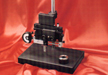
G-600
SETTING FIXTURE MTG
offers a setting fixture for the G-600 internal gage
frame. This fixture enables the operator to readily
set the G-600 frame when finding the "ideal" size
when there are two axis to consider. It is especially
helpful when setting the gage with gage blocks or
plain cylindrical rings. The fixture itself is manufactured
to gage specifications and uses the same mechanism
that is used in our internal gage frame.
(click image for full view) (click image for full view)
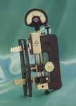
INTERNAL
GAGE STANDS MTG
offers simplicity in measurement. Many times it is
necessary for the user to measure more than one element
of a thread. Shown is an Internal System for
thread measurement. The first gage is set up to measure
the pitch diameter, the second gage measures the diametrical
equivalent of the form (single thread), and the third
measures functional diameter. The gage stand shown
(three risers) is a GS-3. Two risers is a GS-2. One
riser is a OS-1. The OS-1 is expandable to either
a GS-2 or GS-3 simply by purchasing additional risers
because all three stands share a common base. A round
base (GS-O), is available which holds one internal
frame and is used when measuring grooves and bores.
EXTERNAL THREAD INSPECTION
MTG ZONAL METHOD
PITCH (MINIMUM MATERIAL) DIAMETER Inserts
"A" and "J" both contain balls of Best Wire size, and give a
reading which excludes lead error but not angular errors. The
PD. inserts can be used for both left hand and right hand threads.
TAPER AND OVALITY
Use inserts "A" and "J" at intervals along the thread for taper,
and around the thread for ovality.
INCLUDED ANGLE
Use inserts "D" and "J". The ball in "D" is smaller than that
in Pitch Diameter insert "A", and should seat a prescribed distance
deeper. If it does not, angular error is present. The degree
of error and its effect on PD can be determined by using a formula.
UNEQUAL HALF-ANGLES Opposite insert "J", use "E"; then either "F" or "G". "E"
has full flanks, while "F" and "G" are limited to 0.1H contact.
Where half-angles are unequal the thread groove will be tilted,
and "E" will seat more shallow because its broader contact surfaces
will meet greater interference from the tilted groove. The degree
of tilt and its effect on PD. is available through thread spec.
publications.
MINOR DIAMETER
Use inserts "B" and "J".
MAJOR DIAMETER
Concentricity between major and PD is checked by using inserts
"C" and "J", and rotating the workpiece. Major Diameter size,
roundness and taper are checked by a pair of "C" inserts.
FUNCTIONAL (MAXIMUM) MATERIAL DIAMETER
Paired inserts "C' (functional) are Helically Manufactured for
a single PD/Pitch/Lead combination. A separate pair is required
for each combination.
SIMPLE
SETTING METHODS The MTG gage is set "between the balls" or "between the crests'' with gage
blocks or plain master pin/plug gages. No threaded masters are needed.
SETTING THE PITCH DIAMETER INSERTS
The pitch diameter setting equals the pitch diameter (low,
nominal or high) minus ball radius. The ball diameter is
etched on the pitch diameter inserts.
SETTING THE FUNCTIONAL INSERTS
Functional inserts are marked with a specific setting size (example: ID 0.7501).
SETTING MINOR DIAMETER INSERTS
Paired minor diameter inserts are set exactly to the minor
diameter size. When a single minor diameter insert is used
opposite a ''J'' insert to check concentricity, no precise
setting is required. The inserts are brought into contact with the workpiece and
the indicator is read for runout.
SETTING ALL OTHER INSERTS
All contacts (except minor diameter) that are used opposite
contact "J" are marked with a constant (CO) dimension (examples: CO+0.0214; or CO-0.0251). Setting size is equal to the pitch diameter setting
plus or minus the constant dimension.
MTG EXTERNAL GAGE COMPONENTS
(click image for full view)
EXTERNAL
GAGE FRAMES MTG
now offers twenty-two different external gage frames,
ranging in capacity from 0.190 to 18 inches and special sizes are available with greater capacity. All OD inserts are interchangeable
with all external frames. All external frames have
capacities in 1-3/16 inch increments.
Two different
types are offered: GOSR-2 for ranges from 6 inches up to 18 inches in diameter. The GOSR-2 gage frame has a 2 inch reach and approaches the screw thread from the end of the part. GO series has a range from 0.190
to 10 inches. The GO series gage frames approach the screw thread from the side, along the length of the part.
(click image for full view)
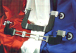
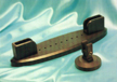
EXTERNAL
GAGE RESTS Many
of our customers have requested some type of rest
or fixture to place the gage frame in after measuring
the part on the machine. Many times the gage was either
knocked on the floor or someone inadvertently placed
objects on the frame. MTG developed the LGR Gage Rest Fixture
to solve this problem. They will not scratch the gage
frames and are adjustable within their range.
External Gage Rest Sizes:
LGR-1 which has
a capacity from 6 inches to 15 inches (shown in photo)
LGR-2 has a capacity from 6 inches to 19 inches
LGR-3 which has a capacity from 6 inches to 23
inches. (Also shown in photo is the GSE-0 Round Gage Base)
(click image for full view)
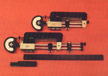
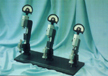
EXTERNAL
GAGE STANDS MTG
offers simplicity in measurement. Many times it is
necessary for the user to measure more than one element
of a thread. (Shown is an External System for
thread measurement which contains three different size frames. This is only to display the size comparison and would never be desired to be combined in this fashion.) The first gage is set up to measure
the pitch diameter, the second gage measures the diametrical
equivalent of the form (single thread), and the third
measures functional diameter.
Available External Gage Stands:
GSE-0: A round base (GSE-O)
which holds one gage frame
GSE-: A stand
with one clamp (expandable by purchasing more clamps)
GSE-2: A stand with two clamps GSE-3: A stand with three clamps
Shown external gage frames:
Far right is a GO-100 (0 inch to 1-3/16 inch capacity)
Middle is a GO-200 (1 inch to 2-3/16 inch, capacity)
Far left is a GO-300 (2 inch to 3-3/16 inch capacity)
Video showing set-up and use of GO-100
This is a non-professional video posted to give a general idea of how this gage is used. Please forgive the non-professional aspects of it.
Comments:
Original Posting: 5/28/2003
Last Revision: 5/5/2018
Error corrections in, or comments about, the above data can be sent to: office@gagecrib.com
Gage Crib Worldwide, Inc.
6701 Old 28th St SE, Suite B
Grand Rapids, MI 49546-6937
Phone: 001-616-954-6581 • Fax: 001-616-954-6583 CONTACT FORMS & INFO