This booklet has been
written to assist users who are desirous of setting
and maintaining their own gages. It will also enable
the user to obtain the maximum benefit from the system
and the greatest economy in the use of the gages themselves.
If the instructions given
are faithfully carried out, the gages will give long
life with accurate performance and trouble-free assembly
of the product.
Most of the maintenance necessary is required to
restore chipped or worn GO (front) anvils. The causes
of this condition may be various but are generally found
to be due to the incorrect application of the gage to
the work. The work should be passed from the front to
the back of the anvils. Care should be taken to set
the dies so that the work passes as easily as possible
through the GO anvils, without passing through the NOGO
(back) anvils.
Do not make the work a
fit in the GO anvils. This not only causes excessive
wear on the anvils and takes a long time to inspect,
but also eliminates the advantages of the tolerances
available on the product.
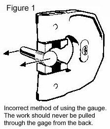
Do not force the work through the GO anvils, AND ABOVE
ALL DO NOT PULL THE WORK THROUGH FROM THE BACK as shown
in Figure 1.
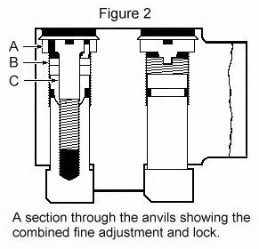
To remove the anvils, first remove the
lead seals at the end of the anvil holes with a small
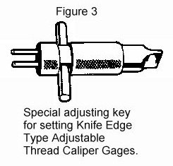
screwdriver or similar tool. Slacken locking screw (Figure
2, A) with the special adjusting key which is available
as an extra accessory (Figure 3). Insert the two pegs
of the key, through the two holes in the locking screw
(Figure 2, A) into the slot in the adjusting screw (Figure
2, B) and remove both locking and adjusting screws together.
Then remove spherical locking cone (Figure 2, C). The
anvils on gages larger than ½ inch can then be removed.
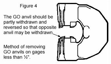
To remove the anvils on gages ½ inch or smaller,
follow the steps above and then push the GO and NOGO
anvils on one side of the gage back against the frame
to the extreme position. One of the GO anvils should
be reversed from its normal position (Figure 4) before
pushing back. The opposite GO and NOGO anvils can now
be removed by tapping the shank with a 5/16 inch diameter
brass rod. This will reduce the danger of chipping the
threads on either anvil.
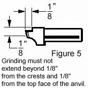
If the gages become worn or damaged they can be repaired.
Because the wear is concentrated at the tip of the anvils,
they can be returned to proper functioning condition
by grinding back the front edge of the anvils. The maximum
grinding must not extend beyond 1/8 inch from the crests
and 1/8 inch from the top face of the anvil (Figure
5).
The anvils should then be reassembled in the frame
by reversing the disassembly procedure. Great care needs
to be taken to avoid damage to the anvils. The locating
abutments on the frame are hardened and must not be
allowed to foul the crests of the thread profile on
the anvils.
The anvils marked with a letter F or an ha figure
should face the same way as the marking on the gage
frame giving the size of the gage.
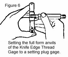
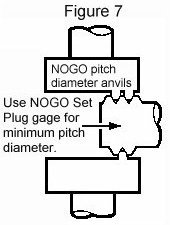
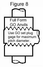
Reset to setting plugs as shown in Figures 6, 7 and
8. NOTE: Setting plugs are ABSOLUTELY NECESSARY when
customers undertake the grinding operation. These are
the same set plug gages that would be used to set adjustable
style thread ring gages. Set the GO anvils using the
GO set plug. Set the NOGO anvils using the NOGO set
plug.
When resetting the anvils it is recommended that the
initial setting be to a core figure of 0.005 inch less
than that finally desired. It will then be normally
possible to make the final adjustments by tension on
the locking screw (Figure 2, A).
We recommend a setting slightly closer than final
and a light tap with a hide hammer on the faces of the
front anvils to relax and disperse any strains on the
same.
After setting and final locking, the gages may be sealed
with lead seals. Users trade marks or initials can be
stamped on the seals by means of a special punch and
is a safeguard against the operator disturbing the setting
of the gage. Seals can be supplied as an extra accessory.
It is a useful precaution to recheck the minor diameter
of the GO and NOGO gaps after resetting and for this
purpose the use of Gage Blocks is recommended. When
using these however, great care must be taken not to
damage the crests of the thread of the anvils, particularly
those of the GO gap.
If it is found necessary to supply new anvils. The
complete gage should be returned to the gage maker.
Comments:
Original Posting: 2/28/2008
Last Revision: 12/1/2014
Error corrections in, or comments about, the above data can be sent to: office@gagecrib.com
Gage Crib Worldwide, Inc.
6701 Old 28th St SE, Suite B
Grand Rapids, MI 49546-6937
Phone: 001-616-954-6581 • Fax: 001-616-954-6583 CONTACT FORMS & INFO

)