ENERSOL S15B CONNECTOR ASSEMBLY DEVICE for ISO 80369-20
The Enersol S15B Connector Assembly Device is the core piece of equipment required for all of the ISO 80369-20 specified tests.
The device is used to apply the required force and torque simultaneously when connecting a reference connector with a test sample. The device may also be used to apply a specified force-only or torque-only.
The Enersol connector assembly device is made from aluminum and hardened steel. The device has a durable and attractive anodized finish. The device has been designed to be compact and easy to use, with no other requirements like an electrical supply or compressed air, etc.
The Enersol (S15B) Connector Assembly Device is suitable for the assembly requirements in:
ISO 80369-20 annexes: B, C, D, E, F, G, H and I; as well as ISO 18250-1 annexes C, D, E, F, G, H and I.
This device is also suitable for carrying out the Resistance to overriding test per ISO 80369, and ISO 18250, Annex H.
We have available the full range of Enersol Reference Connectors for ISO 80369 and ISO 18250 standards.
.
Uses for the Connector Assembly Device (S15B)
The Enersol S15B Connector Assembly Device has two modes of operation. Its primary use is for the assembly of test samples of small-bore connectors and reservoir connectors with their appropriate reference connectors.
Assembly
This is the main mode of operation which is used for the assembly of connectors with reference connectors. This is in accordance with assembly requirements in the methods of ISO 80369-20 Annexes B through I and ISO 18250-1 Annexes B through I.
The S15B device is suitable for the assembly of all the connectors with reference connectors from the following standards:
ISO 18250-1 and ISO 18250-3:
Assembly force for twist-lock connector = not less than 27.5N and after engagement, a torque not less than 0.12Nm.
After engagement for floating or rotating screw-thread locking connectors = 0.25Nm
After engagement for a locking connector with fixed threads = 0.12Nm.
ISO 18250-8, FDIS/ISO 80369-2, ISO 80369-3, ISO 80369-6 and ISO 80369-7.
Assembly Force = 26.5N - 27.5N.
Assembly Torque = 0.08Nm - 0.10Nm for slip connectors, and 0.08 - 0.12Nm for lock connectors
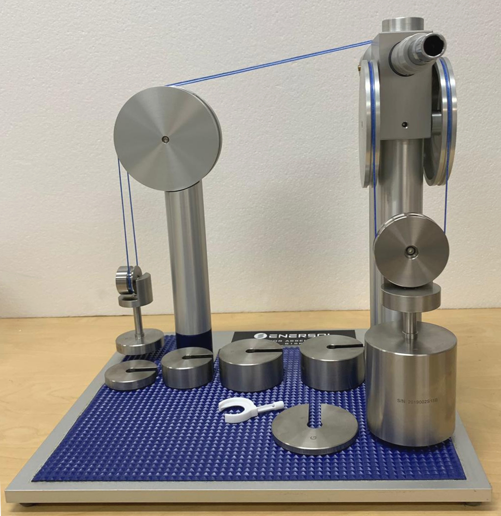
The S15B device is supplied with a fixed known side weight (torque) and a fixed known axial (force) weight. These are the main weights required for assembly. Also supplied with the device are any additional side weights for the resistance to overriding test, and those needed to apply other application forces and torques as required by the ISO 18250 and ISO 80369 standards.
The weights on the S15B device oppose forces and torques applied by the user. When the weights rise from their start position, it indicates that the correct force and torque are being applied.
The device also has a fixed maximum rotation, where it is required to be used (i.e. when assembling non-locking connectors).
Testing
The secondary mode of operation for the resistance to overriding test in Annex H of the ISO 18250-1 and ISO 80369-20 standards.
The S15B is easily set up for the resistance to overriding test by inserting the supplied force application lock (to prevent force being applied), and loading or unloading weights from the side weight to increase or decrease the torque to be applied.
Connector Assembly Device Operation
Assembly (ISO 80369-20 annexes B through I and ISO 18250-1 annexes C through I)
Following the requirements of ISO 80369-20 and ISO 18250-1, the test sample is conditioned prior to testing. In a test environment suitable for the conditions in the standard,
the sample is then prepared with the appropriate reference connector of the application standard.
Following the operation manual (supplied with the device), the user sets the appropriate application force and torque using the supplied weights. The user inserts the hex-end of the reference connector into the S15B Connector Assembly Device. While holding the test sample (or rotating collar of the test sample) the user pushes, and turns, to apply the application force and torque.
For ISO 18250-1:2018 and ISO 18250-3:2018 the assembly force and torque may need to be applied separately.
The device is easily operated by pushing, or turning, as appropriate.
The assembly requirements for
twist-lock connectors are that the force should be applied and then after engagement, the torque should be applied.
After engagement for floating or rotating screw-thread locking connectors a torque is to be applied, and similarly, after engagement for a locking connector with fixed threads a torque is applied. The locking device supplied with the S15B can be used to lock the force in place so that the torque can be applied separately, quick removal of the lock enables the user to apply the force as-needed.
Stress cracking (ISO 80369-20 Annex E / ISO 18250-1 Annex E)
The stress cracking test is essentially a conditioning requirement followed by one or more performance tests (leakage tests) to check that the sample still complies after the stress cracking conditioning.
The sample itself is pre-conditioned according to the Annex E requirements. The sample is then assembled with the appropriate reference connector. The assembled sample and reference connector are then further conditioned according to the stress cracking conditioning requirements in Annex E. Generally, the stress cracking is a longer period of time than the pre-conditioning period. After the stress cracking conditioning period is complete, the appropriate performance test (leakage test or tests) is carried out.
Which leakage test is to be carried out after stress cracking assembly and conditioning?
Small-bore connectors for breathing systems and driving gases applications - FDIS/ISO 80369-2:
BOTH Leakage by pressure decay test and subatmospheric pressure air leakage test.
The leakage by pressure decay test can be carried out using the Enersol Automated Leakage Pressure by Decay Tester model S77A for RESP-125 (R1) connectors or the model S77B for RESP-6000 (R2) connectors.
The subatmospheric pressure air leakage test can be carried out using the Enersol Automated Subatmospheric Pressure Air Leakage Tester model S78A for RESP-125 (R1) connectors or the model S78B for RESP-6000 (R2) connectors.
Small-bore connectors for Enteral applications: ISO 80369-3; and Connectors for intravascular or hypodermic applications:ISO 80369-7.
EITHER: Leakage by pressure decay test OR; Falling drop liquid leakage test.
The leakage by pressure decay test can be carried out using the Enersol Automated Leakage Pressure by Decay Tester (S77/S77B)
The falling drop liquid leakage test can be carried out using the Enersol Falling Drop Liquid Leakage Tester (S16B).
Small-bore connectors for neuraxial applications: ISO 80369-6.
EITHER Leakage by pressure decay test or falling drop liquid leakage test.
Note that the option to choose which fluid leakage method to use is the INTENTION of ISO 80369-6. The standard actually contains a reference error whereby it references only one test (clause 6.1.2) instead of the fluid leakage requirement (clause 6.1.1) where either test can be used. Information from the ISO TC210 committee JWG4 group suggests the standard will eventually be corrected to reference clause 6.1.
The leakage by pressure decay test can be carried out using the Enersol Automated Leakage Pressure by Decay Tester (S77/S77B)
The falling drop liquid leakage test can be carried out using the Enersol Falling Drop Liquid Leakage Tester (S16B).
Connectors for reservoir delivery systems for enteral applications: ISO 18250-3 and Connectors for reservoir delivery systems for citrate-based anticoagulant solution for apheresis applications: ISO 18250-8.
The falling drop liquid leakage test.
This test can be carried out using the Enersol Falling Drop Liquid Leakage Tester (S16B).
Resistance to overriding test (ISO 80369-20 Annex H / ISO 18250-1 Annex H)
The assembly is carried out according to the requirements, after which the user adds or removes side weights to set the required overriding torque. Using the locking device supplied with the S15B, the user locks the force weight into place so that the overriding torque can be applied without supplementary forces.
The assembled connector with reference connector is used and the user inserts the hex-end of the reference connector into the S15B Connector Assembly Device. While holding the assembled test sample (or rotating collar of the test sample) the user turns it to apply overriding torque specified in the application standard. The user checks the sample in accordance with the requirements of the test standard and application standard.
The assembled connector with reference connector is used and the user inserts the hex-end of the reference connector into the S15B Connector Assembly Device. While holding the assembled test sample (or rotating collar of the test sample) the user turns it to apply overriding torque specified in the application standard. The user checks the sample in accordance with the requirements of the test standard and application standard.
Disclaimer:
This data is provided for general information only. The intention is to provide accurate information; regardless; errors may exist in the supplied information. If accuracy is critical, base your final decisions on the data provided in the root documents which are usually copyrighted documents. To purchase a copy of an engineering document visit an Authorized Reseller.
Comments:
Original Posting: 5/11/2013
Last Revision: 2/25/2020
Error corrections in, or comments about, the above data can be sent to: office@gagecrib.com
Gage Crib Worldwide, Inc.
6701 Old 28th St SE, Suite B
Grand Rapids, MI 49546-6937
Phone: 001-616-954-6581 • Fax: 001-616-954-6583 CONTACT FORMS & INFO

 For ISO 18250-1:2018 and ISO 18250-3:2018 the assembly force and torque may need to be applied separately.