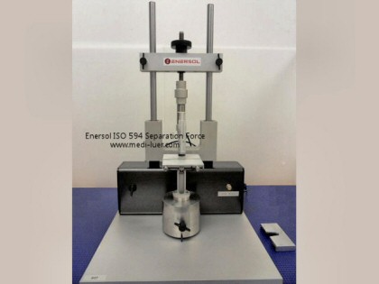
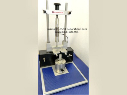
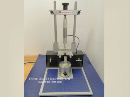
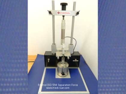
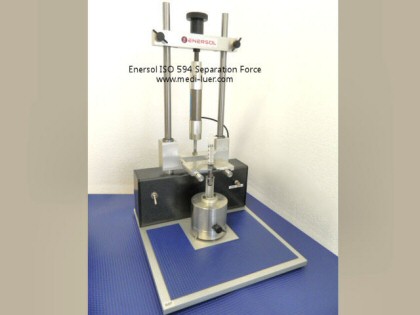
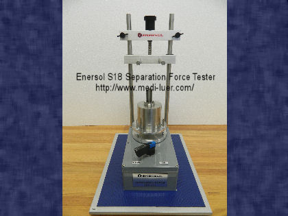
For small-bore connectors and reservoir connectors. The simple to use Enersol Separation Force Test Machine is made from
anodized aluminum, hardened steel and plastic.The Separation Force Test Machine is
designed to use a specialized low friction pneumatic cylinder
that raises and lowers the sample under test.
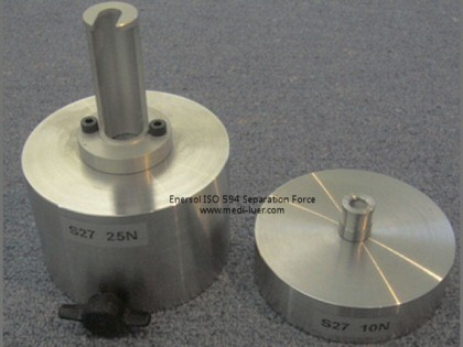
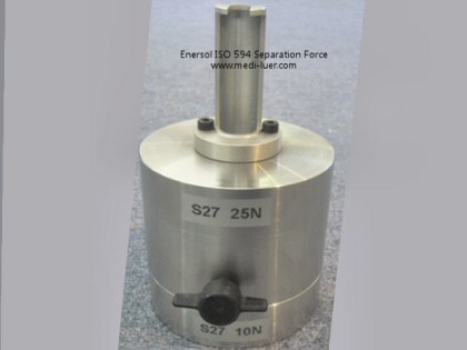
The Separation Force Test Machine is designed to apply a force of 25N and 35N to the
sample under test and comes with a separable weight (25N +
10N).
Uses for the Separation Force Test Machine
The S18B Separation Force Device is used for the Resistance to Separation from Axial Load test method in ISO 18250-1:2018 Annex F and ISO 80369-20:2015 Annex F using the requirements of FDIS/ISO 80369-2 (2018), ISO 80369-3:2016, ISO 80369-6:2016, ISO 80369-7:2016, ISO 18250-3:2018, and ISO 18250-8:2018.
Separation Force Device applies disconnection axial force between:
23N and 25N for Luer slip connectors when following ISO 80369-7:2016 Clause 6.4.
32N and 35N for small-bore connectors when following:
RESP-125 (R1) and RESP-6000 (R1) small-bore connectors of FDIS ISO 80369-2:2018 Clause 6.4.
Enteral small-bore connectors of ISO 80369-3:2016 Clause 6.4.
Neuraxial small-bore connectors of ISO 80369-6:2016 Clause 6.4.
Luer lock connectors of ISO 80369-7:2016 Clause 6.4.
312N and 35N for reservoir connectors when following
ISO 18250-3:2018 Clause 6.5
ISO 18250-8:2018 Clause 5.4.
35N and 36N for reservoir connectors
Those without their own application standard, and following the test requirements of ISO 18250-1:2018 Clause 7.3, and Annex F.
Separation Force Device Operation
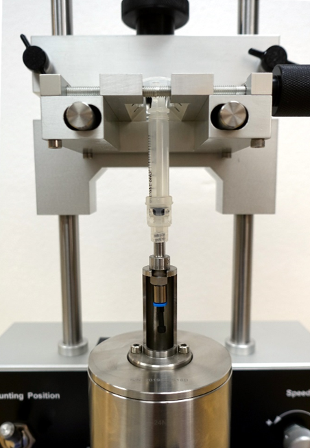
Following Annex F of ISO 18250-1 or ISO 80369-20, as appropriate, the test sample is conditioned prior to testing. In a test environment suitable for the conditions in the standard, the sample is then prepared with the appropriate reference connector of the application standard. The Enersol S15B Connector Assembly Device and Enersol reference connectors can be used to connect the sample with the reference connector.
Once assembled, the user attaches the assembled sample to the grips on the S18B Separation Force Device. The neck of the reference connector is then aligned with the S18B weight so that the
weight will attach to the reference connector during the test.
The user then applies the load using the controls on the S18B.
The separation axial load is slowly applied (within the application range of the standard) until the S18B weight is hanging freely. The weight will be attached to the reference connector, and the base of the weight will no longer be touching the test platform. Thus, the full load is applied to the connection between the test sample, and the reference connector. The user holds this position for the application period in the application standard, and checks whether the connection remains intact.
The weight supplied with the S18B can be separated to apply any of the three different load requirements. When all three pieces are attached together, it applies the heaviest load.
Disclaimer
This data is provided for general information only. The intention is to provide accurate information; regardless; errors may exist in the supplied information. If accuracy is critical, base your final decisions on the data provided in the root documents which are usually copyrighted documents. To purchase a copy of an engineering document visit an Authorized Reseller.
Comments:
Original Posting: 2/11/2020
Last Revision: 2/27/2020
Error corrections in, or comments about, the above data can be sent to: gageguy@gagecrib.com
Gage Crib Worldwide, Inc.
6701 Old 28th St SE, Suite B
Grand Rapids, MI 49546-6937
Phone: 001-616-954-6581 • Fax: 001-616-954-6583 CONTACT FORMS & INFO

-g.JPG)
-g.JPG)
-g.JPG)